Fence Shield Installation
Before heading out, make sure each device is set up on your LNS. Bring your preferred mounting hardware. By default, each Fence Shield comes with 2× UV-proof cable ties. Metal wire (diameter under 4 mm) also works well as an alternative.
Turn off the fence energizer before connecting any cables to the fence wire. Ensure the line is safe to touch before proceeding.
1. Connect the antenna
Screw the supplied antenna onto the SMA connector on the Fence Shield.
Never power on the device without the antenna connected. This can damage the radio.
Position the antenna upright once the device is mounted, with clear space around it where practical.
2. Test device connectivity (LED indicators)
Press and release the exterior button to turn the device on or off while in LoRaWAN coverage.
| LED color | Meaning |
|---|---|
| Turquoise | Connecting to LoRaWAN / sending data |
| Blue | Measuring fence voltage |
| Green (2 blinks) | LoRaWAN connection successful |
| Green (slow-blinking) | Sleeping - no issues detected |
| Red (slow-blinking) | Sleeping - LoRaWAN failed (connection or send) |
The LED turns off after the first few blinks in all states to conserve battery.
Sequence - connection successful, no message sent:
Turquoise → Green ×2 → Blue → Green (slow-blink)
Sequence - connection successful, message sent (alert or heartbeat):
Turquoise → Green ×2 → Blue → Turquoise → Green (slow-blink) or Red (slow-blink, if send failed)
Sequence - connection failed:
Turquoise → Red (slow-blink)
If connection fails, the most common causes are being out of LoRaWAN coverage or a device EUI mismatch on the LNS.
The device restores its last LoRaWAN session from memory on startup for a faster connection, so it may temporarily appear connected even if the gateway is offline. If the status looks unexpected, simply power cycle the device with the button to start a fresh connection attempt.
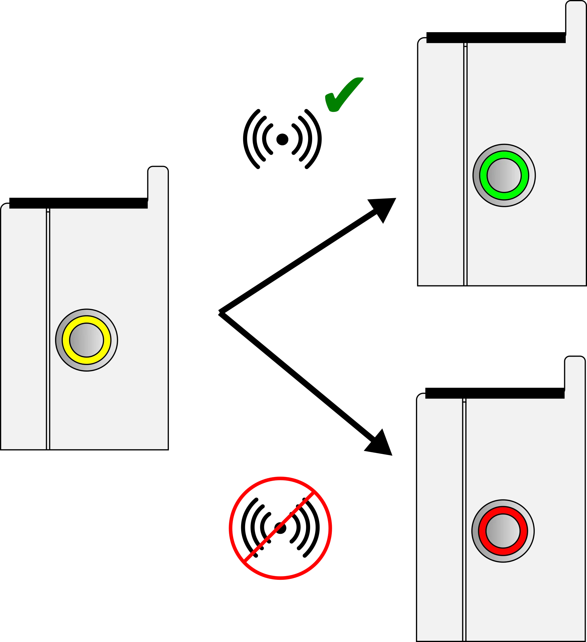
Turquoise = connecting · Green ×2 = connected · Red = failed
3. Choose the mounting location
Pick a fence post or dropper that is:
- In sunlight (for solar charging)
- Within LoRaWAN coverage (higher placement usually improves range)
Mount with an unobstructed view of the sky to support year-round charging. Avoid trees or structures that block sunlight.
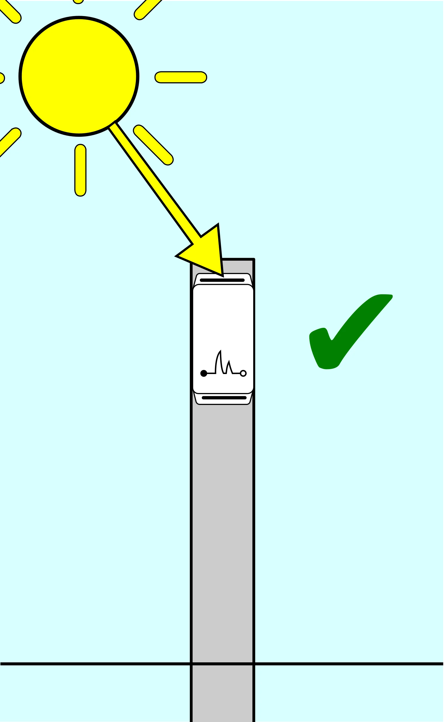
Good: clear sunlight on the solar panel.
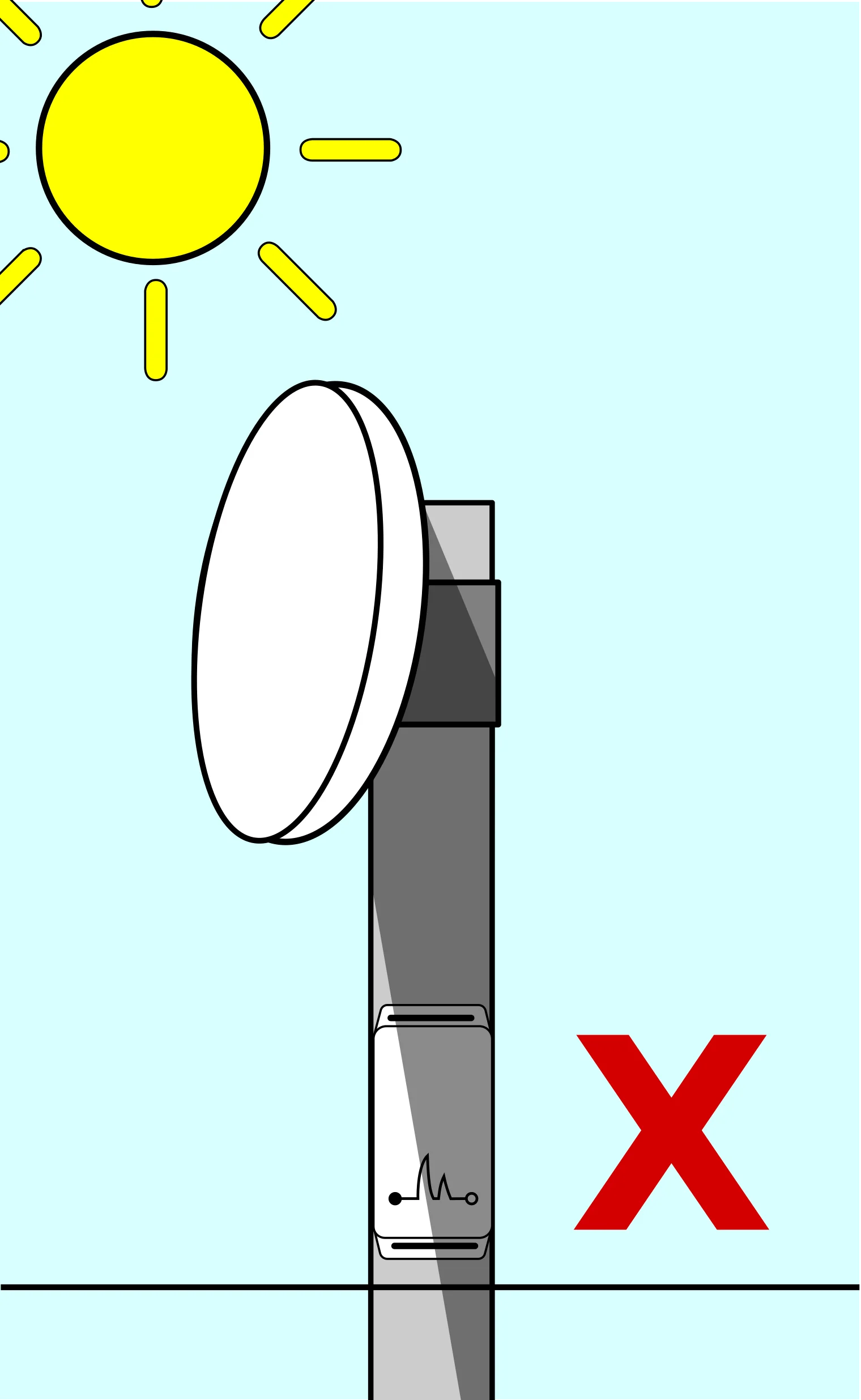
Avoid: shading from trees or structures.
Mount the device as high as practical for better line-of-sight and stronger LoRaWAN performance. Avoid near-ground placement or tall grass.
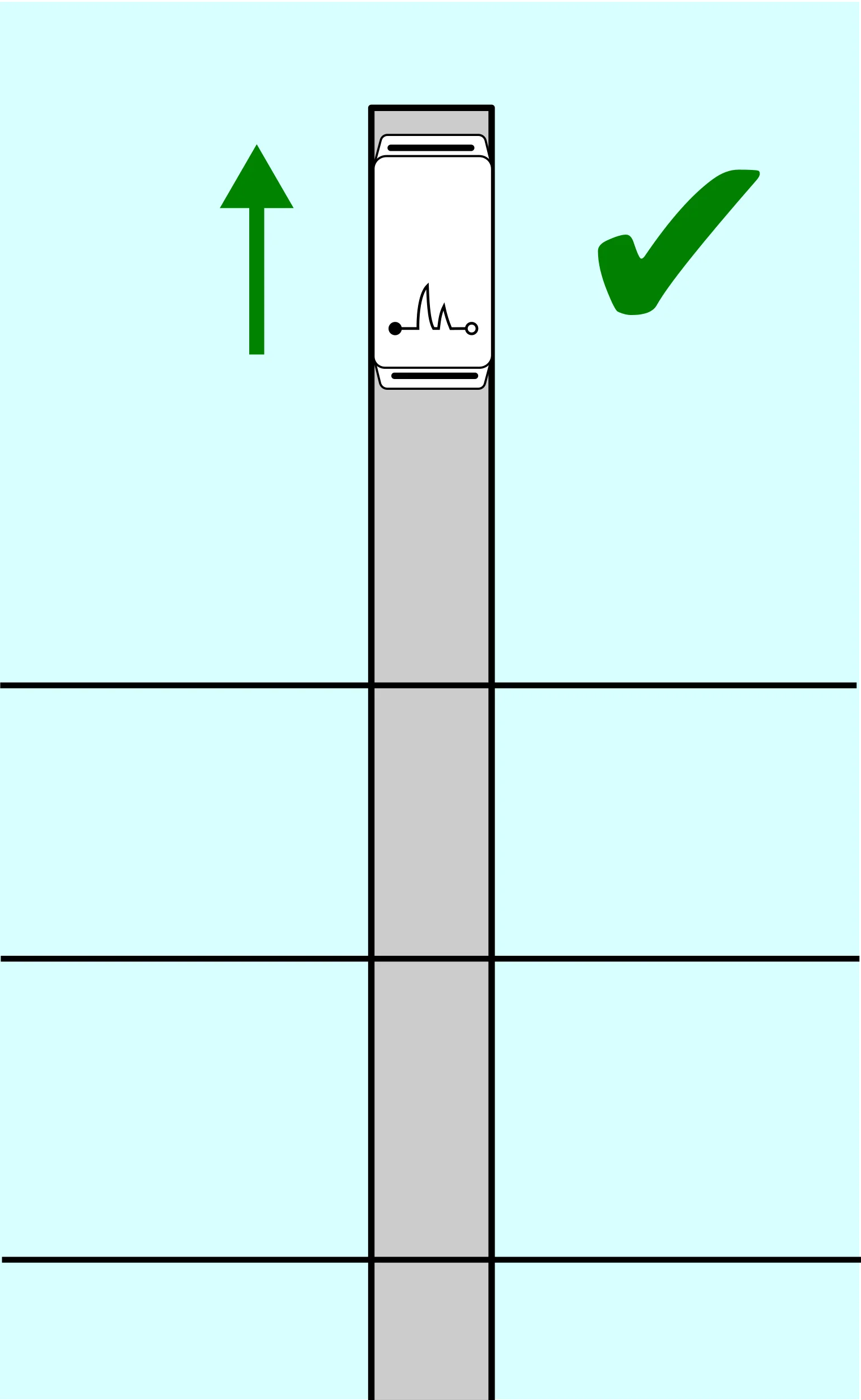
Good: mounted high on the post.
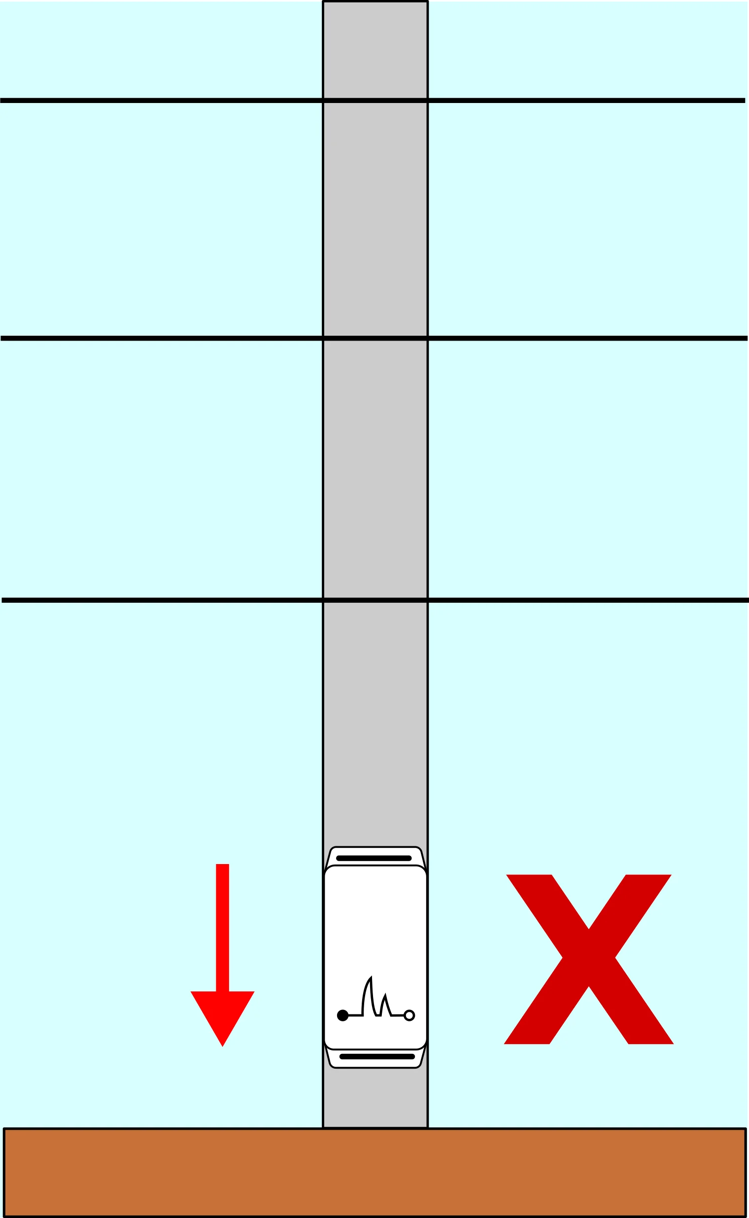
Avoid: low mounting close to the ground.
Record GPS coordinates for each mounted device and map them to the device ID for later dashboard setup.
You can drop a pin in your phone map app or take a geo-tagged photo.
If you are unsure about coverage at the chosen location, briefly power on the device and confirm 2 green blinks after the turquoise connection phase.
4. Mount the device to the post
Before mounting, always make sure the lid is firmly shut and the seal is properly seated for weatherproofing.
Thread cable ties through the four 4 mm enclosure holes (two top, two bottom), then secure the device so it does not slide or rattle. Alternatively, use metal wire.
If using motion detection, mount the devices tightly so they cannot move by accident.
5. Connect the fence wires
With the energizer still off:
- Connect the red device connector to the live fence line.
- Connect the black device connector to the ground line or ground reference.
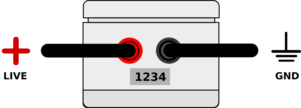
Make sure cables are not under tension and are clear of fence lines and vegetation to prevent arcing or short circuits. Keep all line connections secure for accurate readings.
Once connected, these wires carry the same voltage as the electric fence. Do not touch either wire while the energizer is on.
6. Turn the device on
Press the exterior button to power on the device. You can switch it off any time with another button press.
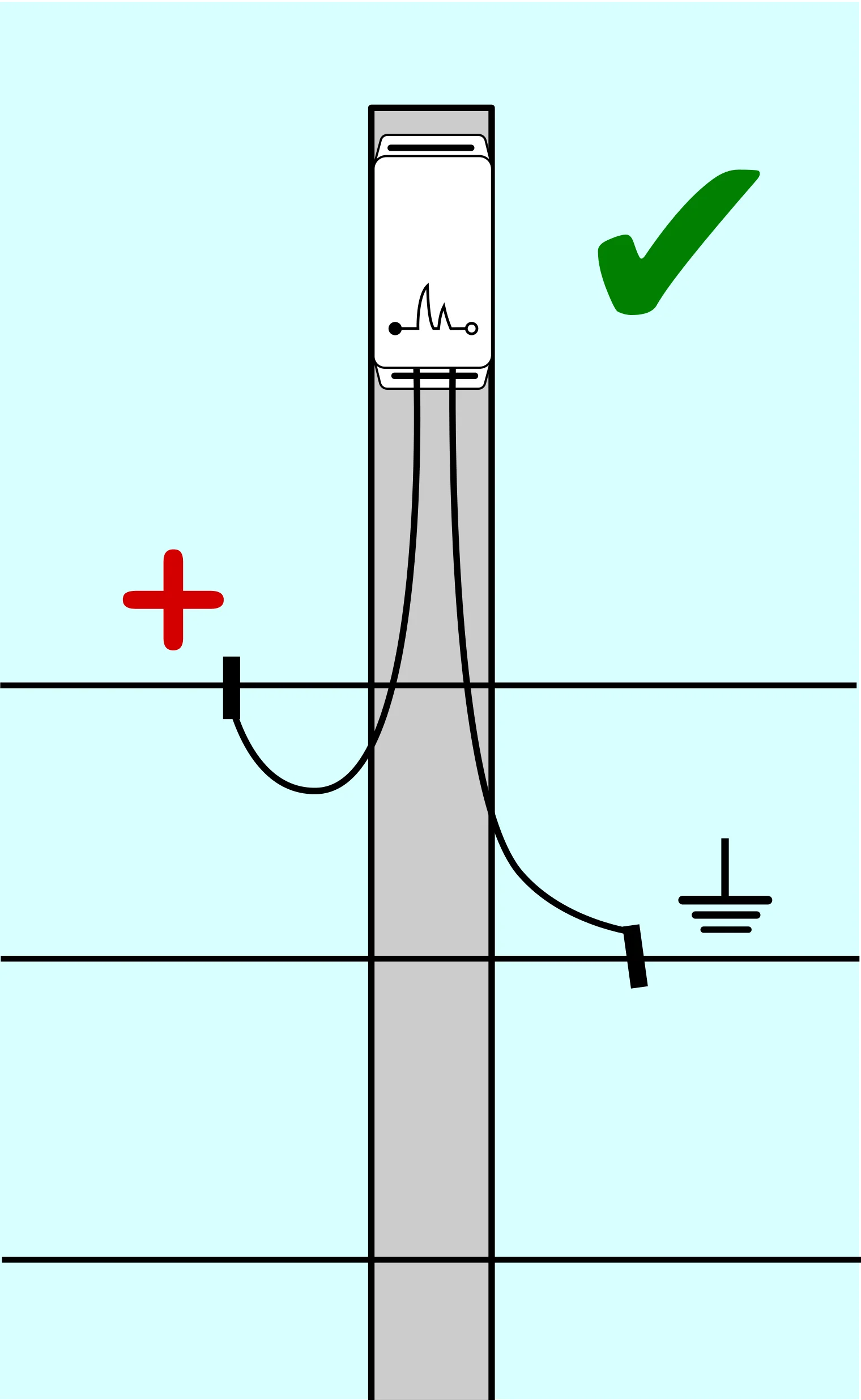
Note: The physical order of live and ground wires can vary depending on the fence configuration.
7. Turn the energizer back on
Clear the area and switch the fence energizer back on. The device is now live and starts monitoring.
The device reports voltage every 60 minutes. If voltage drops below a critical threshold (or recovers), alerts are sent within one minute.